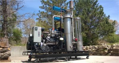
The bioHearth was developed by Richard Woods, owner of Albany Woodworks by iterating smaller scale gasifiers that used residues from the woodworks.
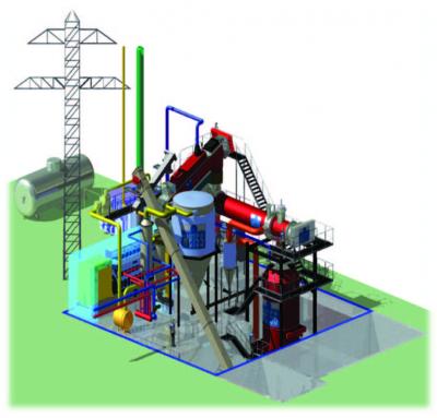
The bioHearth is a down-draft gasifier designed to convert clean residues (sawmill, agricultural, forestry waste) into heat an power.
They currently have a 200kW unit available that will process up to 400/lb of fuel stock per hour, and they are in the process of developing 500kW and 1 MW unit.
It's Friday at the Argos wood gas meeting. On display and running were pickup trucks, mowers, tractor, garden tractors, chunkers and a generator. And let's not forget charcoal making. Saturday should have a larger showing.
In 2013, PT. Gasifikasi Prima Energi (GPE) received a Corporate Social Responsibility (CSR) grant from the Bank Negara Indonesia (BNI), co-funded with USAID-sponsored Indonesian Clean Energy Development (ICED), to develop a 24kW rural electrification project in the area of Munduk in Buleleng Province, Bali. 85 households, 2 temples and a primary school in Munduk village are currently receiving electricity produced.
Over the last year and a half, APL has been collaborating with partners in Italy to develop a fully enclosed, regulation compliant version of the Power Pallet. The new product is intended for general use across the EU, with our inital launch in Italy in October.
Superior Gasification is a newer company that has released the Elite 400 a 50 -60KW gasifier plus generator set designed for small scale power production. The system is built from stainless steel and is designed to run a V10 engine
1st International Conference on Renewable Energy Gas Technology, REGATEC 2014 was a success with 160 participants from 25 countries and 30 exhibitors. Get a free copy of the ISBN numbered conference proceedings by sending your contact details to jorgen.held@renewtec.se.
The conference proceedings contain extended abstracts from 4 plenary speeches, 22 presentations in parallel sessions, 24 poster presentations, and company presentations of the REGATEC Gold and Silver sponsors.
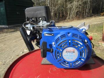
Conversion of a 6.5hp single cylinder Honda clone engine to producer-gas. Timing was advanced and a carburetor was fabricated. These are affordable engines popular with go-cart racers thus there is a pool of performance techniques easily available to tap.
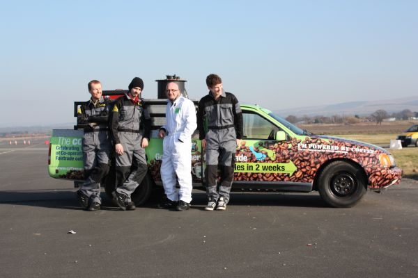
The Coffee bean powered pickup, is a wood gas powered truck commissioned by Co-operative Fairtrade to help highlight the good work being done by supporting Fair Trade products.
This is the third gasifier-car combination built by the coffee car team: Martin Bacon, Colin Davison, Ben Day Preston, and Philip Bacon.
This is the second year that the "Woodgas Meet and Greet" was held in Argos Indiana. With the water tower (Photo 5) acting as a beacon attracting people from across the country to share their knowledge, experience and question with each other. It's easy to say that it was a total success and the Argos Fairgrounds was the perfect setting.
"Chinook Energy's gasification processes provide waste management businesses the ability to create both power and synthetic liquid fuel from a wide range of discarded waste materials. From organic waste substances, a variety of entirely-synthetic fuels can be created: synthetic ethanol, methanol, diesel, gasoline and jet fuel can all be synthesized from an almost-limitless list of feed materials."
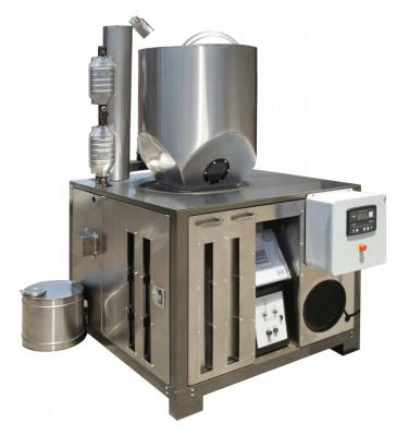
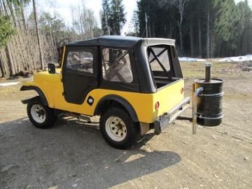
With a Wayne Keith engine modification, this unit starts easily on woodgas.
Fuel consumptions is about 3-4 gallons of sawdust per hour with light, intermittent loads.
The S-80 was an innovative sawdust gasifier produced by Missouri Gasification Systems circa 1980's. It is sized for up to 20hp air cooled applications.
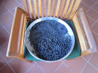
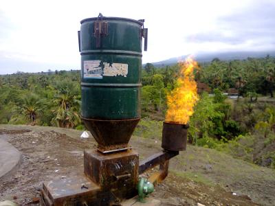
These photos come From Aaron Fishman, who built a small scale gasifier for a cashew enterprise in Indonesia. Their capacity is around 1,000kg/day of which 750kg is waste shells that can be used for fuel and biochar. The biochar will be used to help improve the soils. The company is using the gasifier to reduce their consumption of LPG and to find uses for the cashew shells that are a residue stream from the factory.
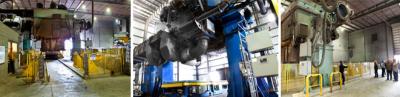
According to the Kansan ICM is decommissioning their pilot plant at Harvey County Transfer Station in Kansas. In the project, the county and ICM explored a number of different feedstock options, including waste paper, urban wood waste, and the county felt that it was a worth while project and worth the time and energy spent on it. They expressed sadness that they could not go forward with a waste-to-energy project at this time.
Weiss from Denmark has a commercial scale CHP plant in Copenhagen, Denmark in operation producing 500 KWe and 1000 MW thermal energy that they are adding to the district heating loop.